

All modifications described herein are done at your own risk !
| Home Garden Railway Digital Conversions | |
For this locomotive, I installed the ZIMO MX65S decoder. I decided to remove the original LGB PCB (printed circuit board) completely. This however requires that all 5 volt bulbs are replaced by 24 volt types. The following schematic shows the connections of the decoder and the lights.
To control the right lower lights and the cab lights, I used the function mapping capability of the ZIMO decoder. Alternatively one can also wire these lights using diodes.
 |
The disassembly of the 20460 is relatively simple. I removed the 4 screws on the
bottom so that I could separate the housing from the chassis. After removing the
walkway and the pipe on the roof, I removed the 4 screws to separate the roof from the housing. Then I removed the original PCB and cut all wiring. |
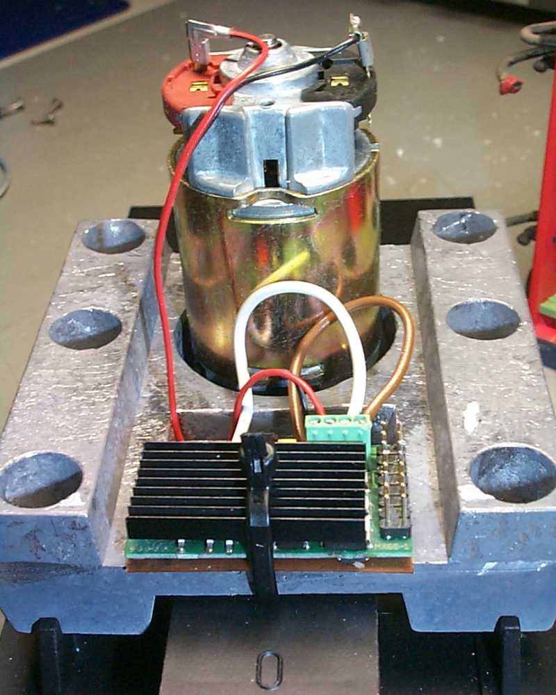 |
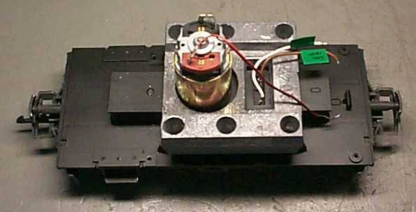
I fastened the decoder with a cable strap firmly to the weight inside the engine.
Next I connected the wires from the track pickup and the motor as shown in the
diagram above. I immediately tried a test run to make sure that the decoder functioned correctly. Once this test was completed successfully, I continued. |
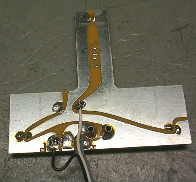 |
I carefully disassembled the two PCBs used for lighting and removed the 5 volt bulbs. Since I wanted to control the right, lower lamp with the help of the ZIMO decoder, I removed the diode and all wiring. Then I soldered a new, sufficiently long three-conductor ribbon cable to the PCB as per the adjacent photo. I also soldered another, sufficiently long ribbon cable to the light used to illuminate the cab. Then I inserted 24 volt bulbs everywhere and reinstalled the PCBs. |
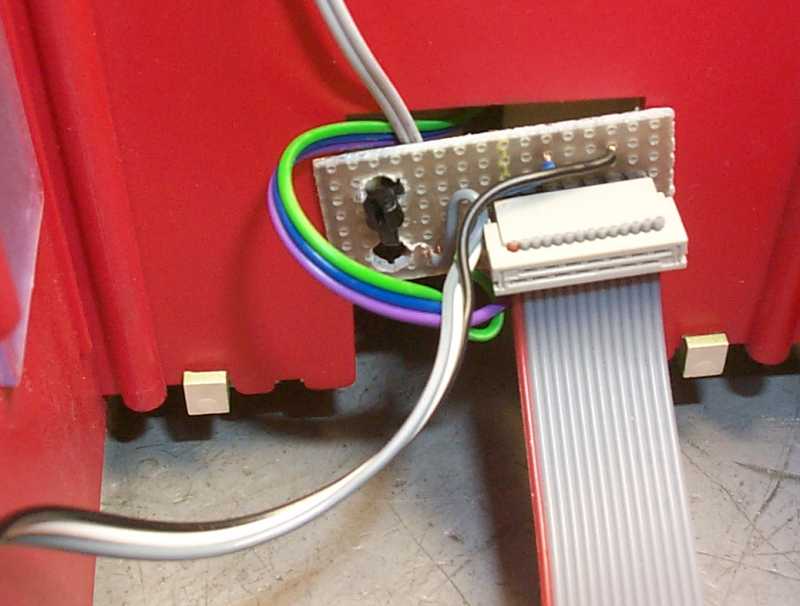 |
To the rear wall of the cab, I fastened a small vectorboard and connected all wires from the lights in accordance with the schematic. This vectorboard serves as pure distribution point and could possibly also be omitted. The vectorboard was connected to the decoder using a ribbon cable. |
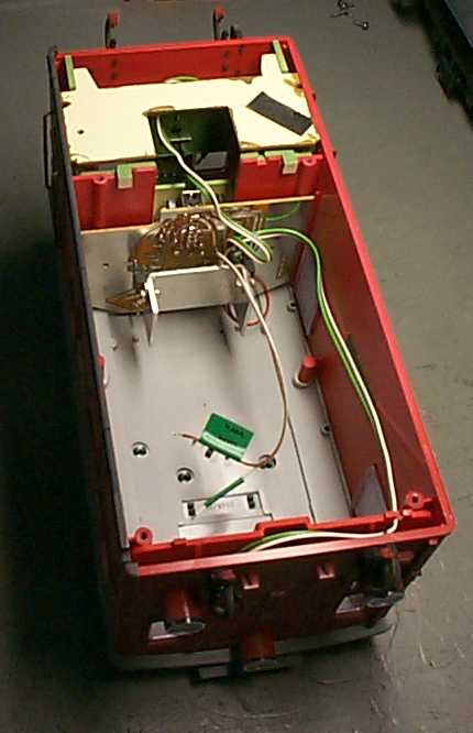 |
The left photo shows the housing with installed roof and attached vectorboard. Note that the engine is shown upside down. |
 |
Next I place the housing on the chassis temporarily and modified some CVs (all
values are hexadecimal). To adjust the motor characteristic of the engine, I changed
CV3=0x03, CV4=0x03, CV9=0x00 (16kHz), CV56=0x21 and CV58=0xA0. For lighting, I programmed
the following values CV33=0x09, CV34=0x42 and CV61=0x6. After everything had been checked to ensure it worked correctly, I reassembled the locomotive and fastened the pipe and the walkway on the roof with a drop of adhesive. |
Translated by Knut Schartmann