
All modifications described herein are done at your own risk !
| Home Garden Railway Conversions |
|
Note: You can view all pictures in a larger version, simply click on it.
The following schematic was used as the basis for this conversion:

| Schematic as a PDF-Document. |
|
I used the decoder Loksound XL from
ESU. I wanted to keep the original 5 volt lamps and therefore added resistors R1..R5 in series. The exact values may have to be adjusted somewhat.
With my particular Digitrax system, the decoder provides 18 volts at the function outputs. A 5 volt
lamp draws about 35ma at normal brightness.
The motors for the uncoupling mechanism require at least 8 volts to operate properly. When using 5 volts,
the mechanism would not move completely to its final end position. It should be noted that IC U2 becomes
quite hot if you operate the coupler several times in quick succession! Switch S1 is required to shut off
the uncoupling motors. The ESU-Locoprogrammer does not provide sufficient current for this during the decoder test.
| Designation | Description | Source | Article Number |
| D1 | Diode 1N4148 75V | Distrelec (CH) | 60 30 16 |
| RL1 | Miniature Relay 24V 1C (Transfer) Contact | Distrelec (CH) | 40 25 34 |
| C1 | Electrolytic Capacitor 100uF 63V | Distrelec (CH) | 80 04 45 |
| C2 | Capacitor 0.1uF 63V | Distrelec (CH) | 82 18 46 |
| R1,R2 | Resistor 120 Ohm | Distrelec (CH) | 70 02 14 |
| R3,R4,R5 | Resistor 330 Ohm | Distrelec (CH) | 70 02 19 |
| U1 | Bridge Rectifier B40C800 I=0.8A U=40V | Distrelec (CH) | 60 00 05 |
| U2 | Voltage Regulator LM2940T-8 "Low-Dropout" Iout=0.5A Eout=8V Case =TO-220 | Distrelec (CH) | 64 53 94 |
| S1 | Switch Single pole ON-ON | Distrelec (CH) | 20 20 00 |
| - | Loksound XL Decoder "Diesel Engine" | ESU Loksound (D) | - |
| - | Speaker 40mm | ESU Loksound (D) | - |
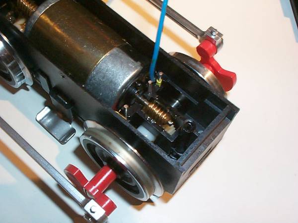 |
This engine is not equipped with a so called decoder interface. One therefore has to bring the second motor connection into the housing. First, you separate the motor block from the housing and open the top of the motor block. Now you can lift out the motor and a wire (blue in the photo on the left) can be soldered to the second motor connection I drilled a hole in the motor cover to feed the wire through. |
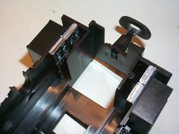 |
I added additional weights in the drive train under the cab. For this I used lead pieces (items 46068 and 46069) from Old Pullman (Switzerland). |
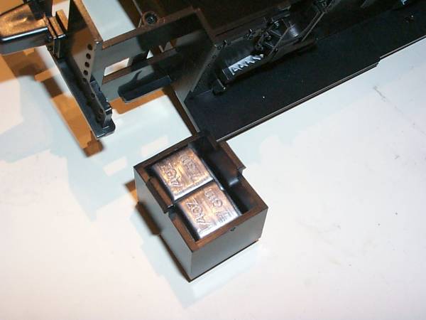 |
I also glued lead pieces inside the two boxes at the front of the chassis. |
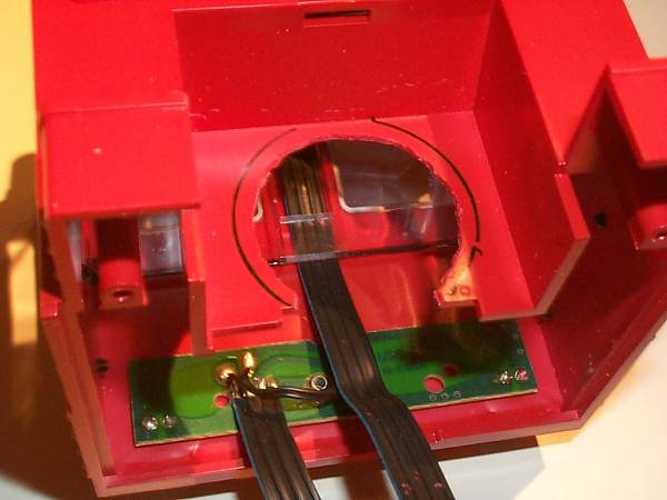 |
To accommodate the speaker, (diameter 40mm, provided by ESU) I cut an opening into the control panel of the cab. |
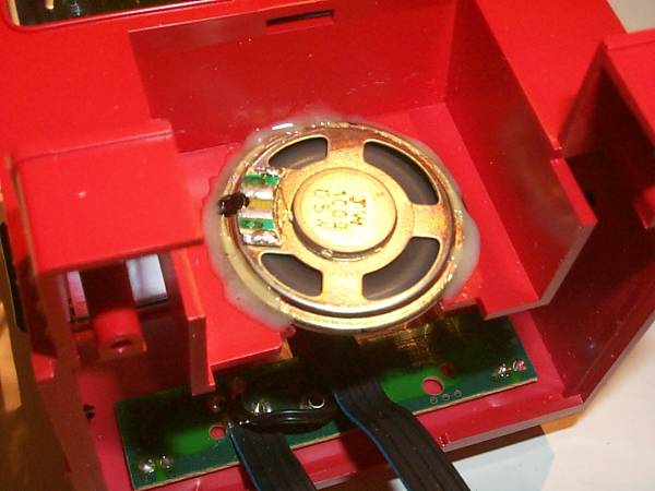 |
I then fastened the speaker using 2-component epoxy glue. |
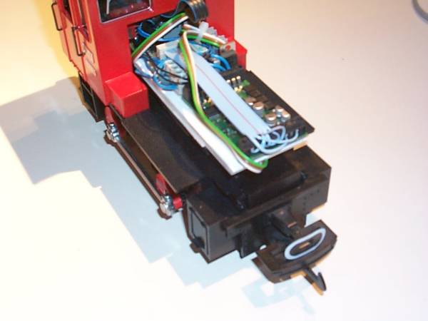 |
On top of the original weight, I first fastened the Original-LGB-metalplate using double-sided
tape and then a thin plastic sheet to provide insulation.. My additional circuit board was fastened
in the rear section of the motor housing. There I attached the original LGB ribbon cable. The decoder
was fastened in the front part of the housing using double-sided tape. The digital conversion was now complete, all that was left to do was the programming of the decoder. |
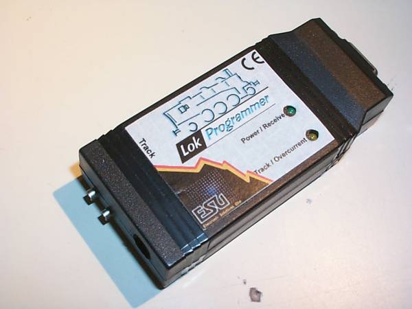 |
The Loksound XL Decoder is very complex, since there is an integrated sound module within the
decoder. Using the normal programming methods via CVs, I could modify all of the decoder settings,
but not the sound parameters. I therefore had to purchase the ESU "Lokprogrammer". Included in
that package is the following: Interface (picture at left), power supply, PC cable for the serial
port and the Windows-Software. For the software it is recommended that you check the ESU Homepage. There you will find the latest version of the "Lokprogrammer". |
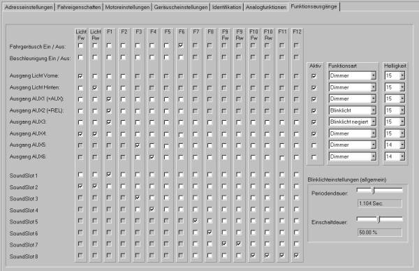 |
The most important part of programming is the function mapping. The adjacent picture (click
on the picture for a higher resolution one) shows the relevant screen shot. Per the above schematic, function button F1 will switch the following outputs: AUX1 (Relay), AUX2 (yellow lamp) and AUX3 (red lamp). Together with the light (both directions), output AUX4 is activated. I programmed the brightness for all outputs at maximum. To flash both lights on the roof alternately, I programmed AUX2 to "Blinklicht" and AUX3 to "Blinklicht negiert". The flashing rate was set to 1.1 seconds. This part of the programming can also be done directly using CVs. |
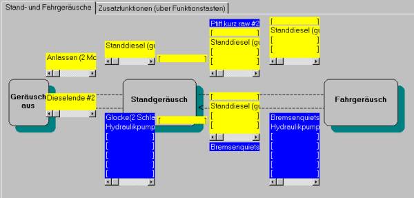 |
Particularly interesting is the possibility to modify the sound parameters and their sequence
using the ESU Lokprogrammer. The adjacent picture (click on the picture for a higher resolution
one) shows the relevant screen shot. The decoder can store a total of 11.4 seconds of sound. The individual sounds (starting the diesel engine, diesel engine idling, ...) are very short and are being repeated indefinitely as required. Thus, even with the decoders limited memory, reasonable sound effects can be created. |
 |
In addition, one can also assign the sound effects directly to the function buttons. The adjacent
picture (click on the picture for a higher resolution one) shows the relevant screen shot. Note that there are interdependencies between the sound 'slots' and the function outputs !! |